Translate:
Quick summary on series and parallel combination of resistors
A resistor is a two-terminal passive electrical component that acts as a circuit element by implementing electrical resistance. Within circuits, resistors reduce current flow and lower voltage levels. To limit the passage of charges in a circuit, most circuits use multiple resistors. The two most basic resistor pairings are series and parallel. The total resistance of multiple resistors is determined by their individual values as well as the way they are connected.
To create more complex circuits, some resistor circuits use a combination of series and parallel networks. This combination is called mixed resistor circuits. Despite the fact that these circuits combine series and parallel circuits, the method for determining equivalent resistance remains unchanged.
Let us look at how total resistance is computed in a circuit with various resistor combinations:
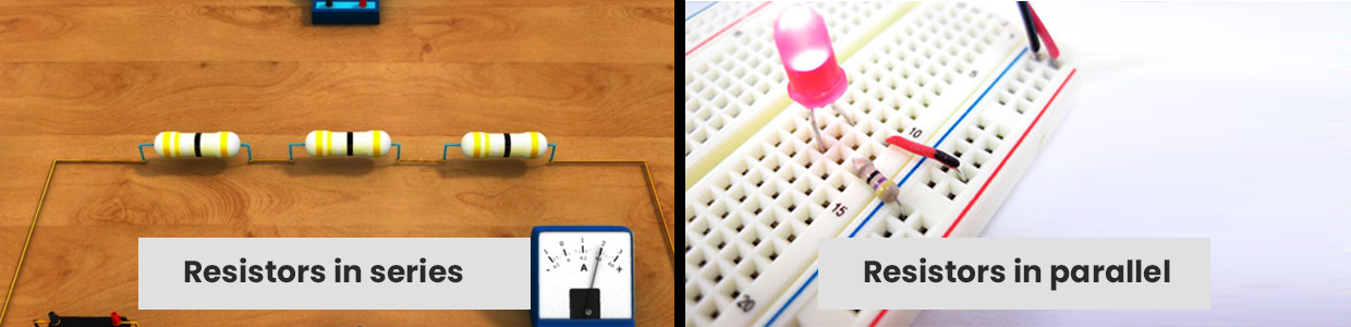
Resistors in series:
A circuit is said to be linked in series, when the same amount of current passes through the resistors. The voltage across each resistor in such circuits varies. If any resistor in a series connection is broken or a fault occurs, the entire circuit is shut off. In comparison to a parallel circuit, the building of a series circuit is easier.
The equivalent series resistance is calculated by:
R (s) = R1 + R2 + ….. + Rn
Where, n is the number of resistors in the circuit.
Take, for example, a resistor with a 100 Ohm electrical resistance is linked to a resistor with a 200 Ohm electrical resistance. Both resistances are linked together in a series. So, the total resistance is calculated as:
R (s) = 100+200
R (s) = 300 Ohm
Here, voltage across each resistor is directly proportional to the resistance, therefore, it is calculated as:
V1 = IR1, V2= IR2 and V3 = IR3 and so on
V = V1+V2+V3+...Vn
When two or more loads are linked in series, they will have a common switch. In school halls and street lighting, this type of connection is used. In compact radios, the tube filaments are frequently connected in series. Automatic house-heating devices have a thermostat, electromagnetic coils, and safety cut-outs connected in series with a power source, and so on. Fuses are linked in a series manner with the device they protect.
Resistors in parallel:
When the voltage across the resistors is the same, the circuit is said to be linked in parallel. The current is branched out and recombined when the branches intersect at a common point in such circuits. In a parallel circuit, a resistor or any other component can be readily attached or disconnected without impacting the other elements.
The equivalent resistance in parallel is calculated by:
1/ R (p) = 1/R1 + 1/R2 + ….. + 1/Rn
Where, n is the number of resistors in the circuit.
Considering the same values as mentioned above, the total resistance when linked together in a parallel circuit is calculated as:
R (p) = 1/100 + 1/200 = (200 + 100) / 20000
1/ R (p) = 300 / 20000
Therefore, R (parallel) = 20000 /300 = 66.67 Ohm
Here, current through each resistor is inversely proportional to the resistance, therefore, it is calculated as:
I1 = V/R1, I2 = V/R2, I3 = V/R3 and so on
I = I1 + I2 + I3 + ... In
The use of parallel circuits is fairly widespread. In homes, various lighting and electrical appliances are linked in parallel so that each lamp or gadget can be powered individually.
Resistance in series and parallel:
Resistor connections that are more sophisticated are sometimes simply series and parallel combinations. This is common, particularly when considering wire resistances. Wire resistors are linked in series with other resistors connected in parallel.
Consider an example, where R1 is connected in series with two parallel resistors R2 and R3. In such cases, the total resistance in series and parallel is calculated as:
R(combined) = (R2xR3/R2+R3) + R1
Comparison between series and parallel resistors:
| Comparison element | Series Circuit | Parallel Circuit |
|---|---|---|
| Component Orientation | Here, the resistors are connected one after the other | Here, the resistors are connected from head to head or tail to tail |
| Current | Same current flows across all the components | Each component have different current value |
| Voltage | Different voltage across different components | The voltage existing across all the components in the circuit is the same |
| Number of paths | Single | Multiple |
| Equivalent resistance | The equivalent resistance in a series connection is always greater than the highest value of resistance. | The equivalent resistance is always less than the sum of the independent resistors connected in parallel |
Conclusion:
Understanding how the resistance varies when connected in different combinations is important before designing any circuit applications. We hope the article has given all the necessary information needed about resistors in parallel and series circuits. Moglix provides a large selection of resistors to help you create various circuits. Visit today and save huge on bulk orders.